- 您现在的位置:买卖IC网 > Sheet目录856 > CTX16-18405-R (Cooper Bussmann)IND PFC 140UH 3.2A TOROID
�� �
�
�Active� PFC� functions� include:�
�?� Active� wave� shaping� of� the� input� current�
�?� Filtering� of� the� high� frequency� switching�
�?� Feedback� sensing� of� the� source� current� for� waveform� control�
�?� Feedback� control� to� regulate� output� voltage�
�Buck,� boost,� flyback� and� other� converter� topologies� are� used� in� active�
�PFC� circuits.�
�The� DC-DC� converter� input� capacitor� also� benefits� from� active� PFC.�
�The� capacitor� can� be� sized� to� filter� the� high� frequency� ripple� of� the�
�active� PFC� circuit� instead� of� a� much� larger� capacitor� that� would� be�
�required� to� smooth� the� 50-60Hz� input.� The� regulated� input� of� the� DC-�
�DC� converter� also� demands� a� lower� range� of� duty� cycle� from� the� DC-�
�DC� converter.� Other� benefits� of� active� PFC� include� increased� “hold-�
�Inductor� Selection�
�Cooper� Bussmann� Coiltronics� ?� PFC� inductors� are� available� for� use� with� a�
�wide� variety� of� PFCs� from� 100W� to� 250W.� They� operate� with� controllers�
�from� several� IC� manufacturers� to� provide� PFC� supply� solutions� that� utilize�
�either� passive� or� active� PFC� applications.�
�Coiltronics� PFC� inductors� range� from� 200� μ� H� to� 1.2mH.� The� standard� input�
�voltage� range� is� 85V� to� 385V� with� different� core� materials� such� as� ferrite,�
�powder� iron� and� Kool-Mu?� to� provide� significant� low� core� loss.� The� E-core�
�and� toroidal� geometries� allow� using� thicker� wire� to� decrease� DC� resist-�
�ance� and� yield� higher� current� capacity.� Many� vertical� or� horizontal� through-�
�hole� mounting� options� are� available� with� an� operating� temperature� range� of�
�–20°C� to� +105°C.�
�over-time.”� Hold� over� (brownout� protection)� benefits� from� always�
�starting� at� the� maximum� voltage;� and� because� energy� in� the�
�capacitor� is� related� to� 1� /� 2� CV� 2� ,� the� capacitor� can� be� much� smaller� than� a�
�capacitor� in� a� converter� without� active� PFC.�
�Boost� Inductor�
�PFC�
�Type�
�None�
�Appearance�
�With� input�
�voltage,�
�switch� or�
�Weight�
�None�
�PF�
�Value�
�50~60%�
�Impact� on�
�Environment�
�Bad�
�PFC�
�Cost�
�None�
�AC�
�F1�
�L2�
�C1�
�L1�
�C2�
�C3�
�PFC�
�B� oost�
�L� ine�
�M� odule�
�C� out�
�F2�
�D� C� /D� C�
�Converter�
�3� .3V� ou� t�
�+�
�fixed� input�
�voltage�
�With� input�
�voltage,�
�Passive� switch� or�
�Heaviest�
�70~80%�
�Better�
�Normal�
�L3�
�F3�
�D� C� /D� C�
�5� V� ou� t�
�+�
�fixed� input�
�voltage�
�Converter�
�Without�
�Active�
�input� voltage�
�Normal� 90~99.9%�
�Best�
�Expensive�
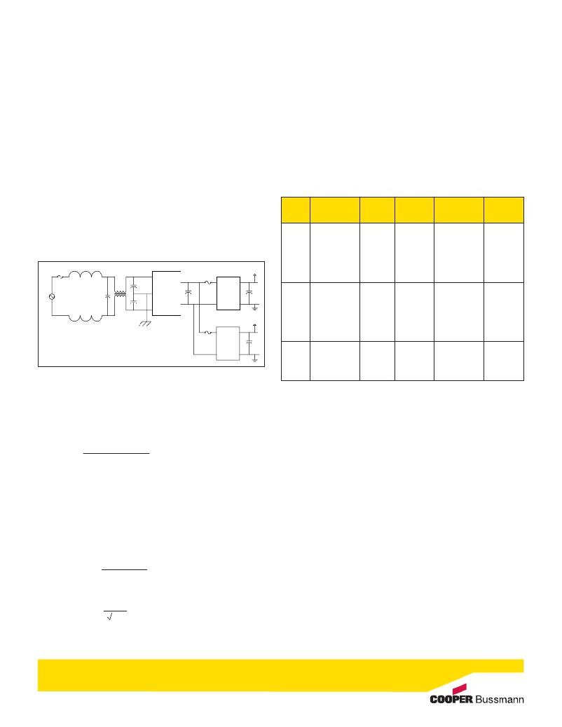
�F� i� g� u� r� e� 3� :� PFC� Boost� -� Typical� application� circuit,� 3.3� &� 5V,� 60W� combined� output� power.�
�The� boost-circuit� based� PFC� topology� is� the� most� popular.� It� is� an�
�economical� solution� for� complying� with� regulations.� The� inductance�
�value� is� selected� based� on� the� desired� current� ripple� in� the� boost�
�inductor.� The� inductance� value� is� expressed� as� follows.�
�switch�
�T� a� b� l� e� 1� :� Comparison� of� passive� and� active� PFC� versus� no� PFC.�
�Fuses�
�AC� Input� Line� Fuse�
�L=�
�VpKin (min) * d(max)�
�fs� *� Δ� i�
�Product� safety� standards� written� by� Underwriters� Laboratories� (UL)� and� the�
�International� Electrotechnical� Commission� (IEC)� require� fuses� for� primary� AC�
�power� protection� and� secondary� protection� against� any� catastrophic� failure�
�where:�
�?� VpKin� (min)� is� the� peak� minimum� input� voltage�
�?� fs� is� the� switching� frequency�
�?� Δ� i� is� the� ripple� current�
�?� d(max)� is� the� maximum� duty� cycle� expressed� as:�
�within� the� input� filter� capacitors,� PFC� boost� module,� output� electrolytic�
�capacitors� (Cout)� or� the� DC-DC� converters.� The� PFC� boost� module� usually�
�does� not� contain� overcurrent� protection;� if� a� short-circuit� is� applied� across�
�its� output� terminals,� there� is� no� internal� circuit� opening� device� to� safely�
�interrupt� the� power.� Without� fuse� protection� in� the� AC� input� line� (see�
�fuse� F1� in� Figure� 3),� the� boost� converter� is� not� protected.�
�Fusing� the� DC-DC� converter� input� lines� is� essential� for� protection� against� a�
�d(max)� =�
�1-� VpKin� (min)�
�Vo�
�where� Vo� is� the� output� voltage�
�catastrophic� DC-DC� converter� failure� (see� fuses� F2� and� F3� in� Figure� 3).�
�Protecting� the� DC-DC� Converter�
�Although� the� primary� input� line� fuse� will� eventually� activate,� DC� fuses�
�The� rms� boost� inductor� current� is� expressed� as:�
�positioned� right� at� the� input� to� the� DC-DC� converters� will� limit� the� energy�
�IL� (rms)� =� in�
�I (pk)�
�2�
�A�
�delivered� by� the� hold-up� capacitors� (Cout)� and� will� prevent� failure� to� the�
�PFC� boost� module.�
�发布紧急采购,3分钟左右您将得到回复。
相关PDF资料
CTZ3E-50C-W1-PF
CAP TRIMMER 4.5-50PF 25V SMD
CV31A080
CAP TRIMMER 2-8PF 350V TH
CV31A180
CAP TRIMMER 5.5-18PF 350V TH
CV31B110
CAP TRIMMER 2.5-11PF 350V TH
CV31C250
CAP TRIMMER 8-25PF 350V TH
CV31D350
CAP TRIMMER 9-35PF 200V TH
CV31E600
CAP TRIMMER 15-60PF 200V TH
CV35A090
CAP TRIMMER 2.5-9PF 100V TH
相关代理商/技术参数
CTX16-18484
制造商:TI 制造商全称:Texas Instruments 功能描述:A 0.9-A Constant Current Supply with PFC for 100-W LED
CTX16-18484-R
功能描述:固定电感器 PFC W/AUX WDG 1mH 3.1A PK RoHS:否 制造商:AVX 电感:10 uH 容差:20 % 最大直流电流:1 A 最大直流电阻:0.075 Ohms 工作温度范围:- 40 C to + 85 C 自谐振频率:38 MHz Q 最小值:40 尺寸:4.45 mm W x 6.6 mm L x 2.92 mm H 屏蔽:Shielded 端接类型:SMD/SMT 封装 / 箱体:6.6 mm x 4.45 mm
CTX16-18610-R
功能描述:固定电感器 TRANSFOR HALF BRIDGE 1.8mH EF25 THT
RoHS:否 制造商:AVX 电感:10 uH 容差:20 % 最大直流电流:1 A 最大直流电阻:0.075 Ohms 工作温度范围:- 40 C to + 85 C 自谐振频率:38 MHz Q 最小值:40 尺寸:4.45 mm W x 6.6 mm L x 2.92 mm H 屏蔽:Shielded 端接类型:SMD/SMT 封装 / 箱体:6.6 mm x 4.45 mm
CTX16-18625-R
功能描述:固定电感器 BUCK W/AUX WDG700uH @1A PK THT RoHS:否 制造商:AVX 电感:10 uH 容差:20 % 最大直流电流:1 A 最大直流电阻:0.075 Ohms 工作温度范围:- 40 C to + 85 C 自谐振频率:38 MHz Q 最小值:40 尺寸:4.45 mm W x 6.6 mm L x 2.92 mm H 屏蔽:Shielded 端接类型:SMD/SMT 封装 / 箱体:6.6 mm x 4.45 mm
CTX16-18702-R
功能描述:固定电感器 PFC 150uH @7.8A PEAK 2WIRE THT RoHS:否 制造商:AVX 电感:10 uH 容差:20 % 最大直流电流:1 A 最大直流电阻:0.075 Ohms 工作温度范围:- 40 C to + 85 C 自谐振频率:38 MHz Q 最小值:40 尺寸:4.45 mm W x 6.6 mm L x 2.92 mm H 屏蔽:Shielded 端接类型:SMD/SMT 封装 / 箱体:6.6 mm x 4.45 mm
CTX16-18833-R
功能描述:耦合电感 500uH 3A PEAK RoHS:否 制造商:Bourns 电感 - 并联:10 uH 电感 - 串联:40 uH 容差:20 % 最大直流电流:2.08 A 最大直流电阻:0.0826 Ohms 端接类型:SMD/SMT 工作温度范围:- 40 C to + 105 C 系列:SRF0703 类型:Dual-Winding Shielded Power Inductors
CTX17-17640-R
功能描述:固定电感器 IND SHLD DRM 1.45MM .47UH RoHS:否 制造商:AVX 电感:10 uH 容差:20 % 最大直流电流:1 A 最大直流电阻:0.075 Ohms 工作温度范围:- 40 C to + 85 C 自谐振频率:38 MHz Q 最小值:40 尺寸:4.45 mm W x 6.6 mm L x 2.92 mm H 屏蔽:Shielded 端接类型:SMD/SMT 封装 / 箱体:6.6 mm x 4.45 mm
CTX17-18765-R
功能描述:固定电感器 200nH, 100kHz, 2 Phases, SMT RoHS:否 制造商:AVX 电感:10 uH 容差:20 % 最大直流电流:1 A 最大直流电阻:0.075 Ohms 工作温度范围:- 40 C to + 85 C 自谐振频率:38 MHz Q 最小值:40 尺寸:4.45 mm W x 6.6 mm L x 2.92 mm H 屏蔽:Shielded 端接类型:SMD/SMT 封装 / 箱体:6.6 mm x 4.45 mm